Cross-AZ Disaster Recovery with Nutanix Cloud Clusters on AWS
Ensure Business Continuity for workloads with NC2 on AWS and cross-AZ replication
Organizations running critical workloads in AWS require robust disaster recovery capabilities to ensure business continuity. While AWS Availability Zones (AZs) provide built-in redundancy within a region, applications still need comprehensive protection against AZ failures. Nutanix Cloud Clusters (NC2) on AWS addresses this need by enabling enterprises to implement sophisticated disaster recovery strategies across AZs.
NC2 delivers near-synchronous replication with RPOs as low as 1 minute, combined with automated failover and failback capabilities. This ensures minimal data loss and quick recovery during outages. The solution’s ability to extend Layer 2 networks between AZs while maintaining application-consistent snapshots provides a seamless recovery experience without the complexity typically associated with cross-AZ migrations.
One of the key advantages of using NC2 for disaster recovery is the ability to perform non-disruptive DR testing. Organizations can verify their recovery procedures without impacting production workloads, ensuring confidence in their business continuity plans. The entire DR operation can be managed through Prism Central, providing a unified management experience that simplifies the complexity of cross-AZ disaster recovery.
Network Mobility Benefits with NC2 DR
One of the most powerful features of NC2’s disaster recovery capabilities is its ability to maintain network consistency across different environments. This significantly simplifies DR operations and reduces application downtime:
IP Address Preservation
- VMs maintain their IP addresses across DR operations, whether failing over between:
- Different AWS Availability Zones
- Different AWS Regions
- On-premises data centers and AWS
- Back to the source environment during failback
- No DNS updates or application reconfigurations needed after failover
- Applications continue to work without modification or IP address changes
Network Configuration Benefits
- Layer 2 network extension eliminates the need for complex networking changes
- Application dependencies remain intact during and after failover
- No requirement to update firewall rules or security group configurations
- Seamless preservation of internal DNS settings
- Support for both NAT and No-NAT networking options
Operational Advantages
- Simplified DR testing without impact on production workloads
- Reduced risk of human error during failover operations
- Faster recovery times due to elimination of network reconfiguration steps
- Consistent networking experience across hybrid cloud environments
- Easy failback operations with maintained network configurations
This network mobility is particularly valuable for:
- Applications with hard-coded IP addresses
- Complex multi-tier applications
- Environments with strict security and compliance requirements
- Legacy applications that cannot be easily modified
- Solutions requiring frequent DR testing
Solution components
For this example we deploy two NC2 clusters into a single AWS VPC. This helps simplify the configuration by not requiring linking separate VPCs. This also lowers cost compared to transferring data across VPC peering connections or via Transit Gateways.
Note that separate NC2 clusters cannot share subnets. Therefore each NC2 cluster will get its own private and public subnets as per the below. We deploy a public subnet and three private subnets in each AZ.
The public subnet is only used for external access. The first of the private subnets is for the bare-metal nodes, the second for Prism Central management server and the third for Flow Virtual Networking - the overlay networks used to ensure the same IPs are kept for the workload VMs when switching AZ.
1
2
3
4
5
6
7
8
9
10
11
12
13
14
15
16
17
18
19
20
21
22
23
24
25
26
27
28
29
30
31
VPC: nc2-vpc
├── Internet Gateway: igw-1234abcd
├── NAT Gateway: nat-5678efgh
│   └── Located in: subnet-public-1a (ap-northeast-1a)
├── Route Tables
│   ├── Public Route Table: rtb-public
│   │   └── Routes
│   │       ├── 0.0.0.0/0 → igw-1234abcd
│   └── Private Route Table: rtb-private
│       └── Routes
│           ├── 0.0.0.0/0 → nat-5678efgh
│           └── Local (intra-VPC)
├── Subnets
│   ├── Availability Zone: ap-northeast-1a
│   │   ├── Public Subnet: subnet-public-1a
│   │   │   ├── Associated Route Table: rtb-public
│   │   │   └── Contains: NAT Gateway
│   │   └── Private Subnets
│   │       ├── subnet-private-1a-1
│   │       ├── subnet-private-1a-2
│   │       └── subnet-private-1a-3
│   │           └── All associated with: rtb-private
│   └── Availability Zone: ap-northeast-1c
│       ├── Public Subnet: subnet-public-1c
│       │   └── Associated Route Table: rtb-public
│       └── Private Subnets
│           ├── subnet-private-1c-1
│           ├── subnet-private-1c-2
│           └── subnet-private-1c-3
│               └── All associated with: rtb-private
Cost considerations
When implementing cross-AZ disaster recovery with NC2 on AWS, consider these cost components:
- Infrastructure costs:
- NC2 cluster running costs in both primary and DR AZs (includes compute and storage)
- Data transfer costs:
- Initial data sync costs
- Cross-AZ data transfer charges for replication traffic
- DR testing and failover-related transfer costs
- Network costs:
- NAT Gateway charges (per AZ)
Cost optimization strategies:
- Choose appropriate replication intervals based on workload requirements
- Optimize VM sizing in the DR site
- Consider using AWS Savings Plans for long-term commitments
- Monitor and adjust replication policies based on actual RPO needs
Note: For specific pricing details, please refer to the AWS pricing page as costs vary by region and usage patterns.
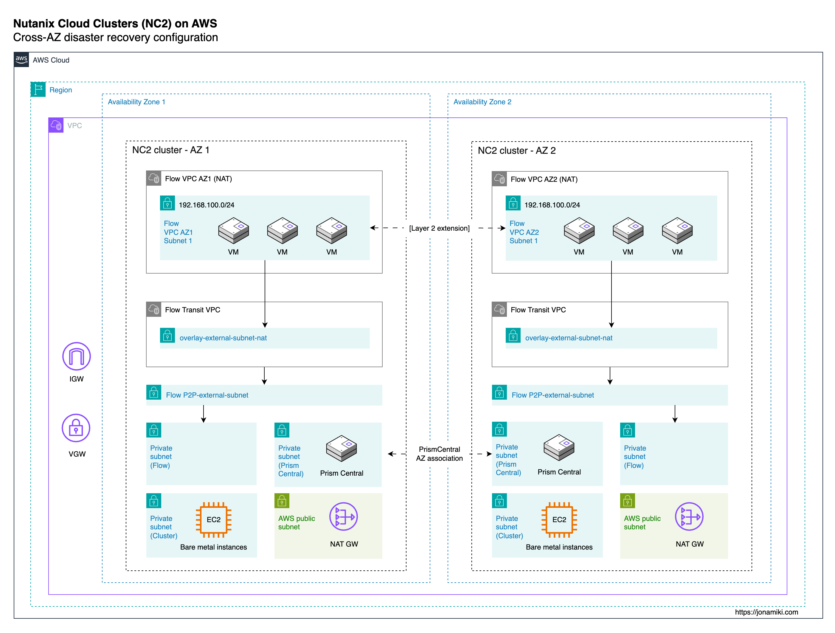
Architecture
The below diagram illustrates the components involved and how they interact.
Prerequisites
For this configuration, please deploy a VPC with one public and three private subnets in each AWS AZ. Then deploy an NC2 cluster into each AZ and check the box for enabling Flow Virtual Networking in the deployment wizard.
A note on no-NAT overlay networks
The recommended multi-AZ configuration would be to have two NAT gateways - one in each public subnet in each AZ. However, that would require separate routing tables for the private subnets in AZ1 vs AZ2. This is fine if there is no plan to use no-NAT networks on NC2. However, if no-NAT is used, routes for those subnets will be added to the main and the public route tables ONLY. If the NC2 cluster in AZ2 uses a route table separate from the main route table, it won’t get the required routes when no-NAT networks are created.
Therefore, in this case we have used a single route table - the main route table, for all private subnets in both AZs. This means that in case of AZ1 experiencing downtime, there is a need to manually update the default route in the main route table to point to the NAT GW in AZ2.
Environment
In this example we use the below software versions
| Entity | Version |
|---|---|
| NC2 on AWS Prism Central | pc.2024.3.1 |
| NC2 on AWS AOS | 7.0.1 |
Overview of steps
We configure the solution in the following way
- Link the two Prism Central instances
- Create the VPCs and subnets for the workload VMs
- Connect the workload VM subnets with Layer 2 extension
- Enable Disaster Recovery on both clusters
- Create a category for the VMs to be protected and attach it to the VMs
- Configure a DR policy
- Create a DR plan
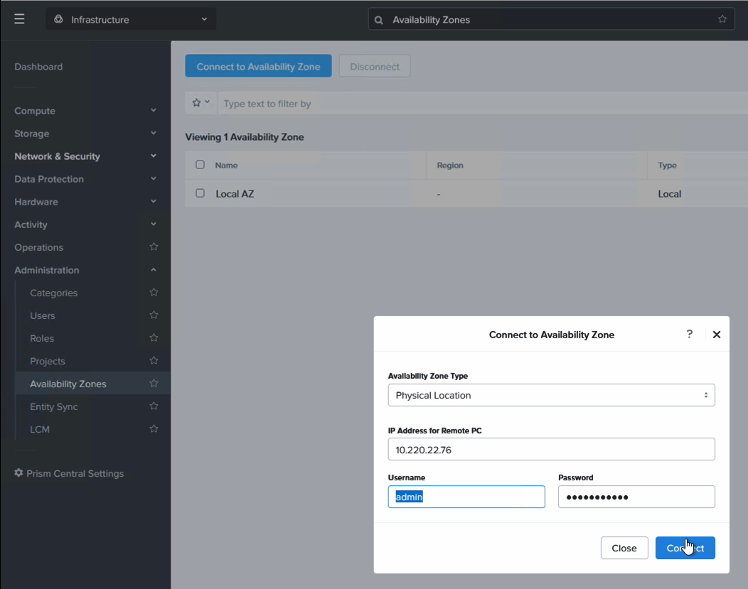
Step 1: Link the two Prism Central instances
Linking the PC instances is a 2 min job. Please ensure the PC AWS Security Group for both clusters allow traffic so the PC instances can communicate. The AZ type is “Physical location”
Step 2: Create the Nutanix Flow VPCs and subnets for the workload VMs
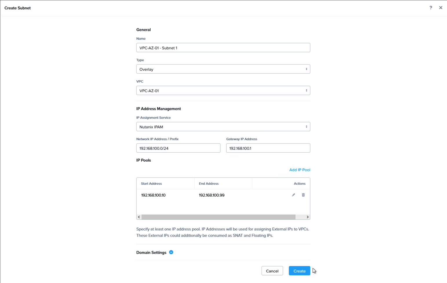
Create the Flow VPCs to hold the VMs on both sides. I have labeled mine with AZ1 and AZ2 to identify them more easily. In each VPC, create a subnet with the same CIDR and default GW but different DHCP scopes.
In our example we used the below settings:
Subnet in AZ1
| Entity | Value |
|---|---|
| CIDR | 192.168.100.0/24 |
| DGW | 192.168.100.1 |
| DHCP scope | 192.168.100.10-99 |
Subnet in AZ2
| Entity | Value |
|---|---|
| CIDR | 192.168.100.0/24 |
| DGW | 192.168.100.1 |
| DHCP scope | 192.168.100.100-199 |
Firstly we create the VPC. Create one in each AZ:
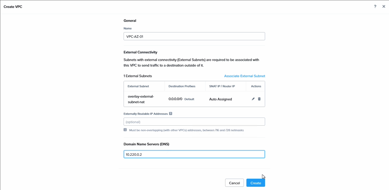
Then we create a subnet in each VPC using the settings above, or of course whatever aligns with the subnets you wish to create in your particular environment.
Step 3: Connect the workload VM subnets with Layer 2 extension
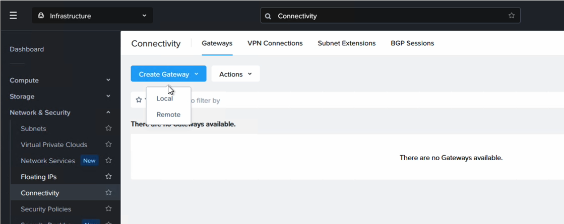
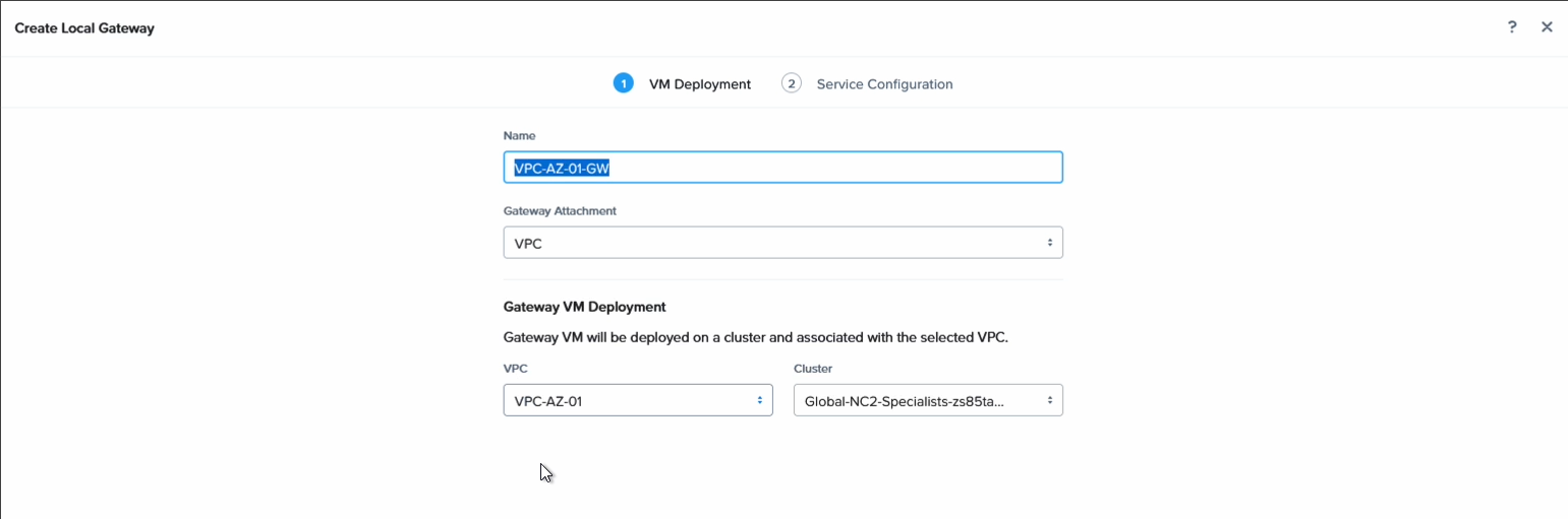
Since we want to ensure that VMs in each AZ can talk to each other, even if they are on the same subnet, we extend the network using Nutanix Layer 2 extension. For this we create a local gateway in each NC2 cluster and associate each with the VPC in that AZ.
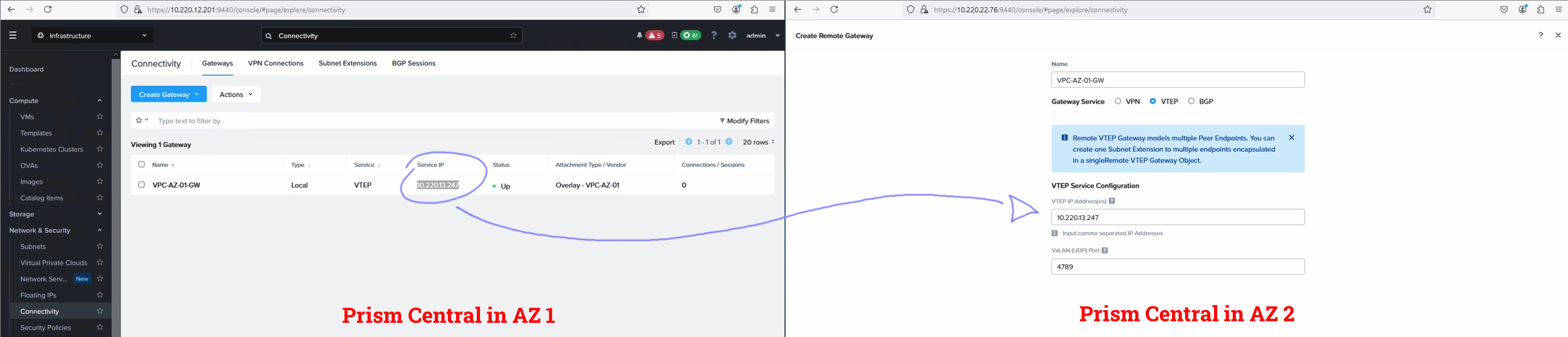
We add a name to identify it
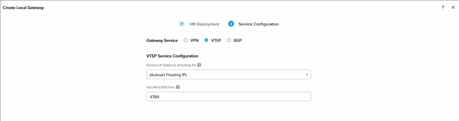
Then set it to VTEP and set the UDP port. Feel free to leave it to the default unless there is need to customize it.
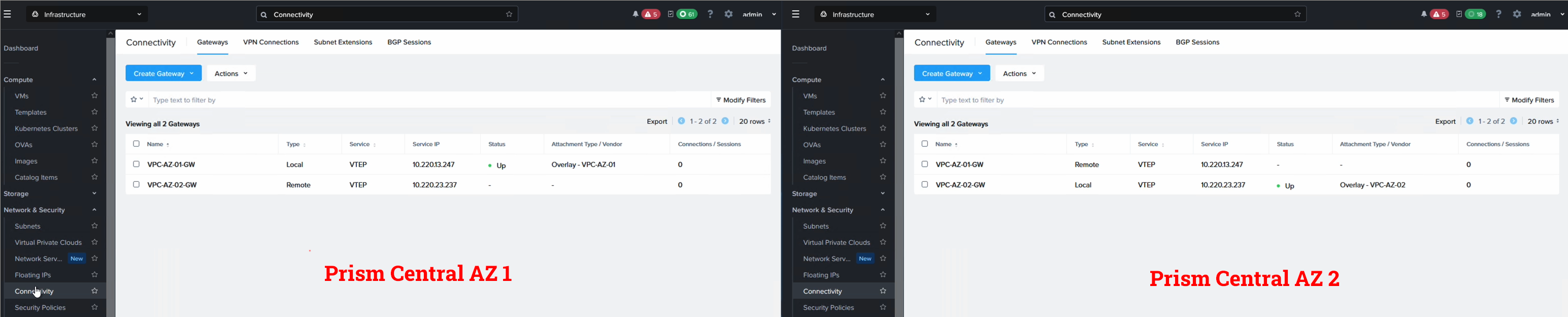
After the local network gateways come up they will list a service IP. Copy it and register it as a remote gateway on the other cluster. You register the IP of the gateway in AZ1 as a remote GW in AZ2 and vice versa.
It should look something like this when done.
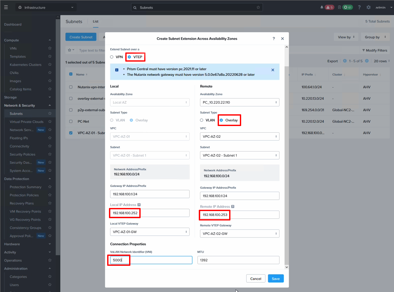
Now all that is left is to stretch the subnet and we have finished the Layer 2 extension settings. From the Subnets screen, highlight the subnet to be stretched and select “Extend” from the Actions menu. Select your local and remote gateways and give each GW an IP on the subnet to be extended.
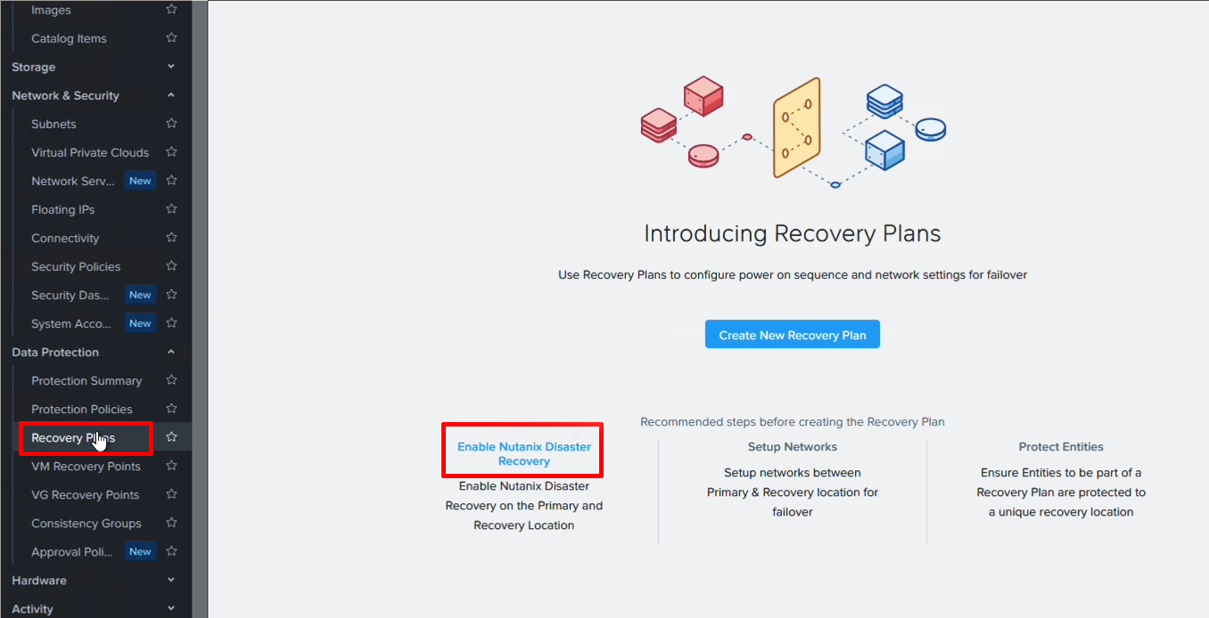
Step 4. Enable Disaster Recovery on both clusters
This is literally a click of a button. The setting can be enabled either from the Prism Central settings menu or as here - from the DR plan screen.
Step 5. Create a category for the VMs to be protected and attach it to the VMs
Prism Central makes it really easy to manage different groups of VMs by having categories as a way to lable them. We use it here to group the VMs we want to have included in the DR policy.
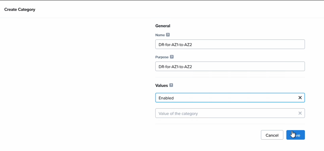
Go to “Administration”, “Categories” and click on “New Category”. Enter in a name and a value. We’ll filter on this name later so please pick something easy to remember.
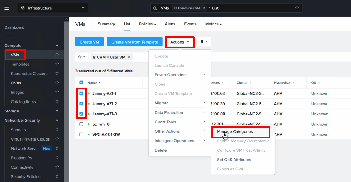
Next we need to assign this category to the VMs we want to protect. Navigate to VMs, higlight the VMs to be protected and select Manage Categories from the Action menu. Then search for your category and assign it to the VMs.
Step 6. Configure a DR policy
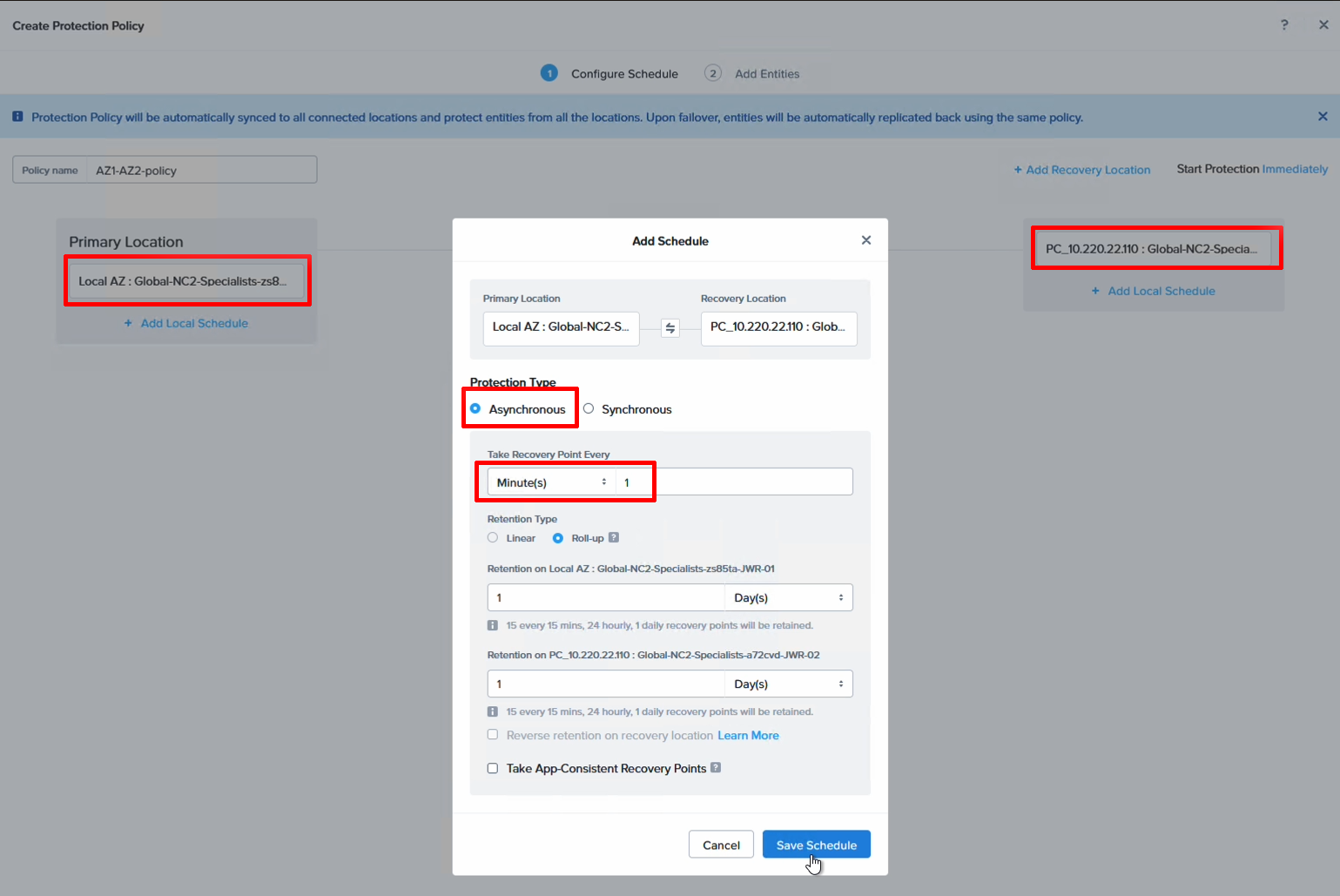
The DR policy decides the source, destination, schedule and scope (what VMs to include), so it is perhaps the most important part of the DR configuration. We select our local cluster as the source, the remote cluster as the destination and then set a schedule. Since we do DR between two AZs in the same AWS region we can set this to be quite low. In this case we use 1 minute snapshots.
Navigate to “Data Protection” and “Protection Policies” to add a new policy.
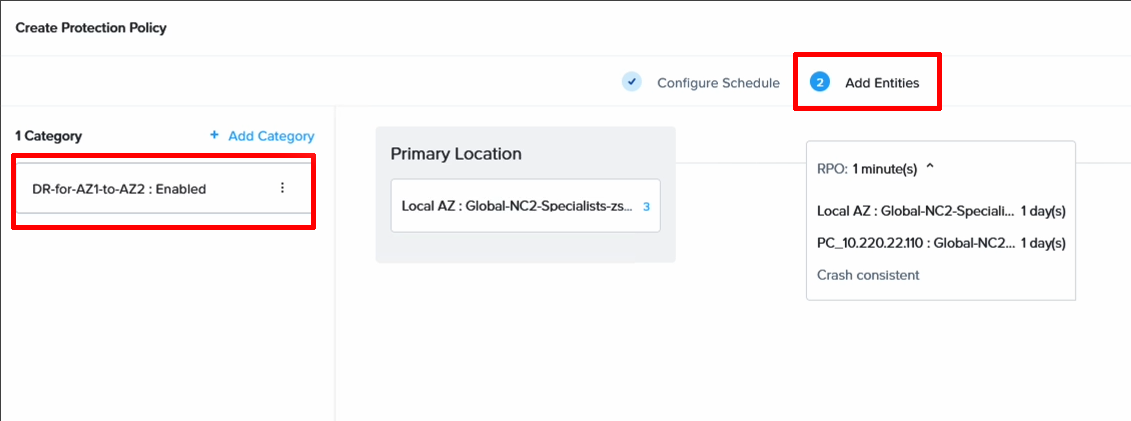
Now it’s time to associate our Category with the DR policy so we can easily manage the VMs we want to be included. Add your category and save the DR policy.
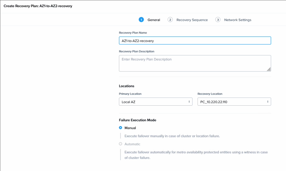
Step 7. Create a DR plan
Now all that remains is to create the DR plan which will allow us to fail over our VMs. Go to Data Protection, select Recovery Plan and create a new plan. In this case we do this on the AZ1 cluster, so we add the source as our local cluster and for the destination we select the cluster in AZ2.
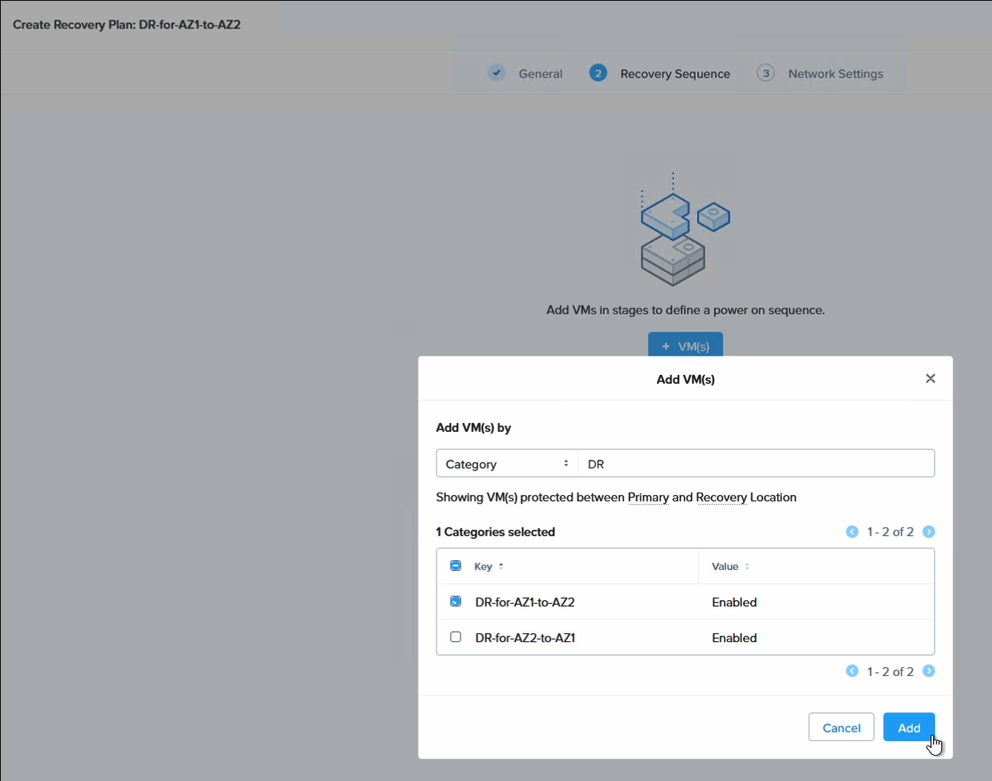
Here we also select our category to apply the recovery plan to the VMs we grouped earlier. As you can see, it is possible to select individual VMs as well, so one can be more granular here and only select a subset of the VMs backed up earlier. This provides a lot of flexibility when it comes to what to fail over and how.
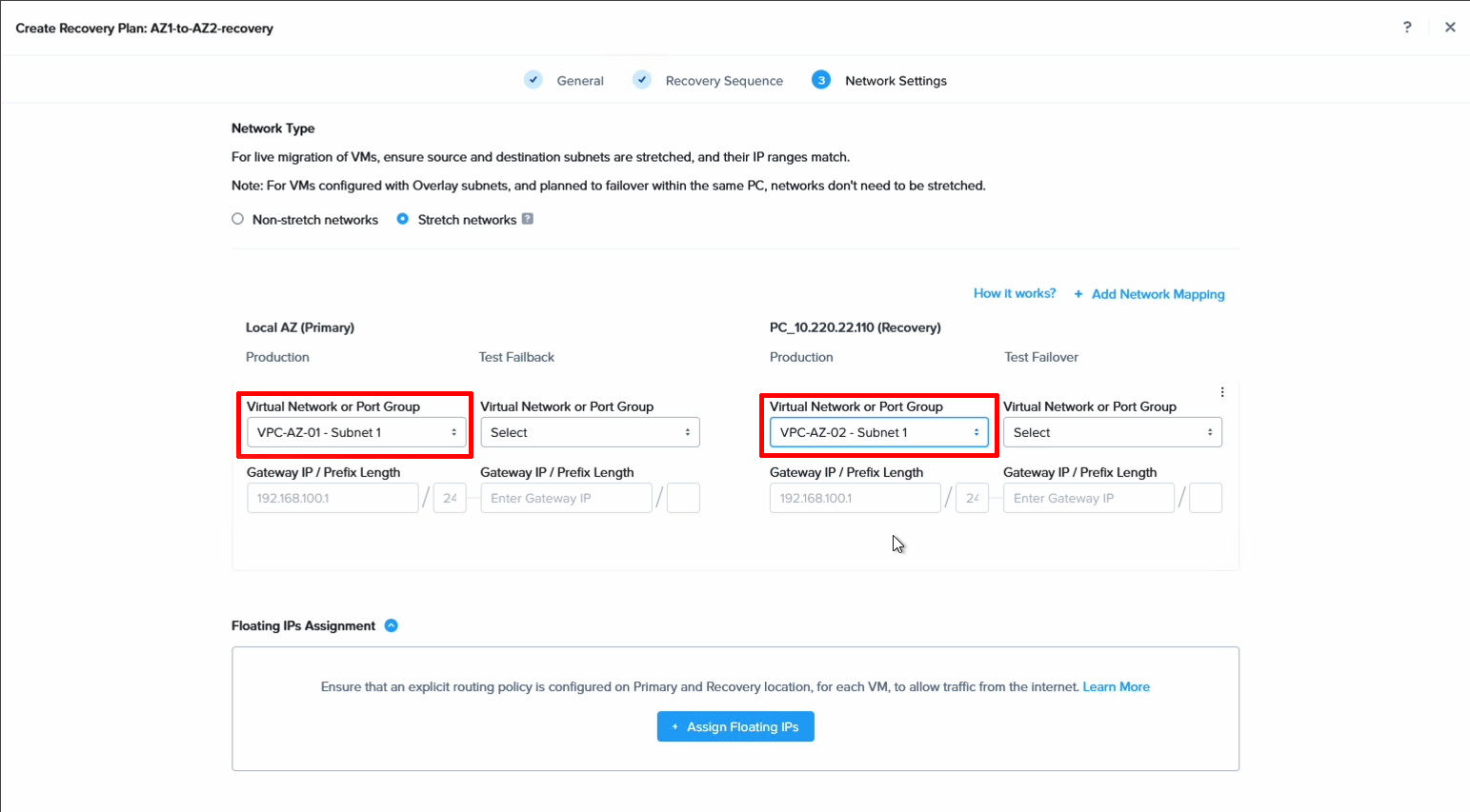
Finally we set the network mapping. Basically, what network should the VMs be mapped to when failing over to the other cluster.
Note that it’s also possible to configure test networks here to do failover tests in full isolation, without affecting running workloads. This makes it easy to do regular failover rehearsals, also during business hours.
Verifying the DR configuration by failing over from AZ1 to AZ2
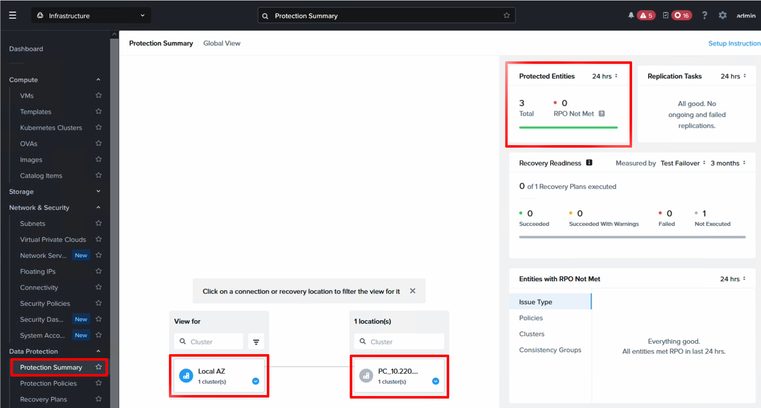
We can now view the protection status from the Protection Summary screen and our three VMs are shown as protected. We’re now ready to do a fail over from AZ1 to AZ2.
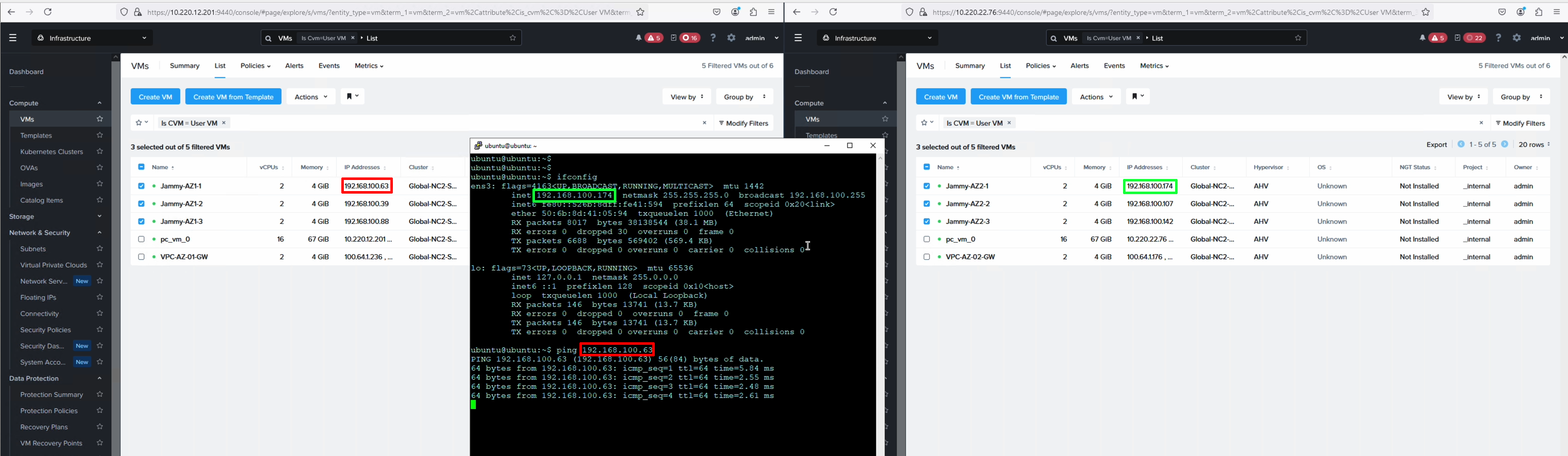
We start a ping from a VM in AZ2 to a VM in AZ1 - a VM which we will fail over.
Since we have stretched the network these VMs are attached to, it is possible to show how the latency will change as the VMs switch AZ.
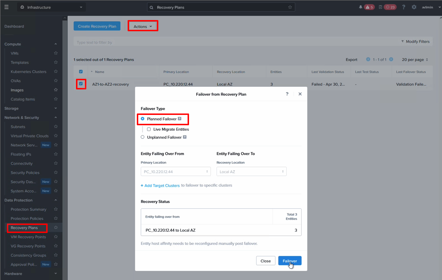
To fail over, open your recovery plan and select Failover.
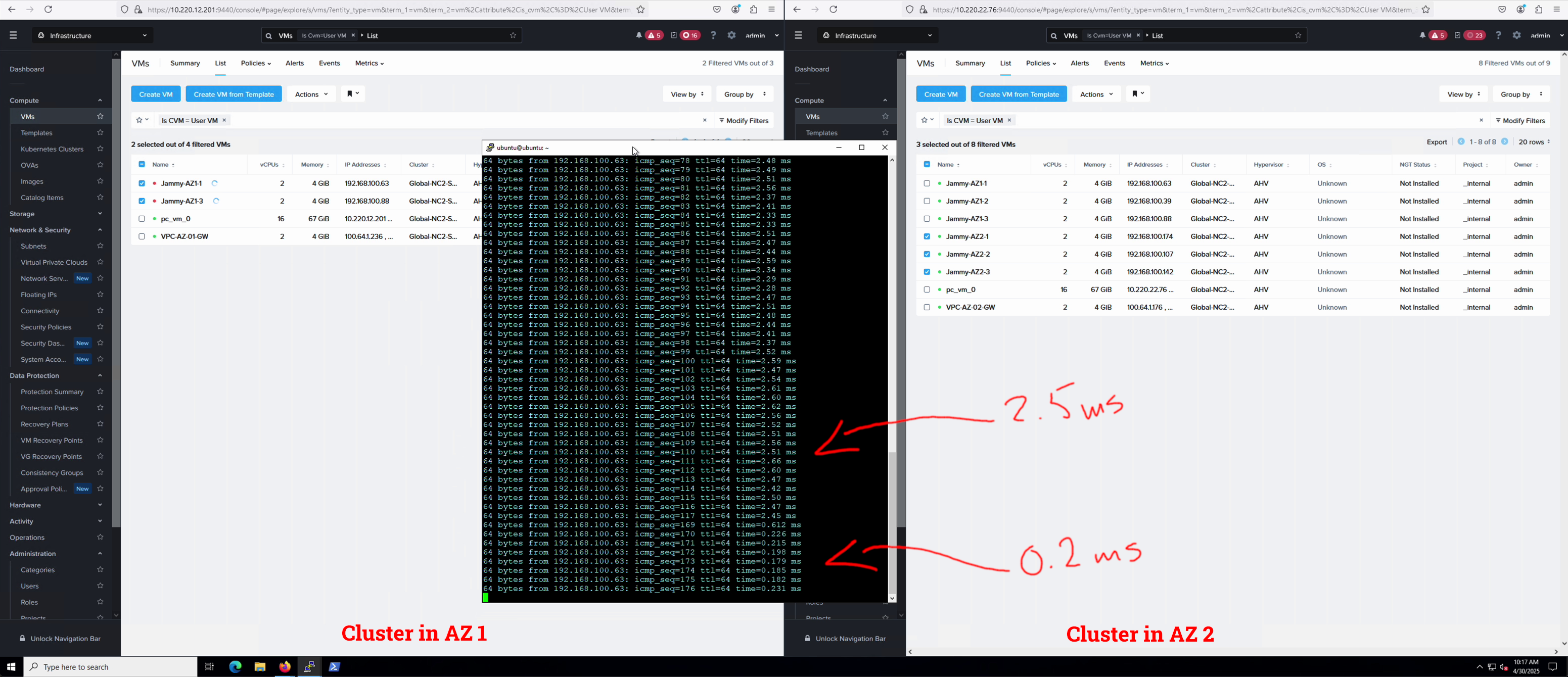
We can see the ping time reducing drastically from 2.5 ms to less than 1 ms after failing over to AZ 2.
Conclusion
This guide has shown how to configure cross-AZ replication between two NC2 on AWS clusters. Hopefully it has been useful.